NONDESTRUCTIVE TESTS
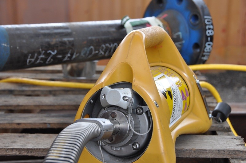
Radiographic Test (RT) is a technique used for volumetric flaw detection. Short wavelength electromagnetic radiation such as X-rays and Gamma Rays penetrate the thickness of the component and a photographic image is recorded on films placed on the other side of the component. Exposed films are then processed, developed and dried and the radiographic images are viewed on high intensity film viewer for presence of discontinuities and evaluated according to reference acceptance standard.
- Conventional Method
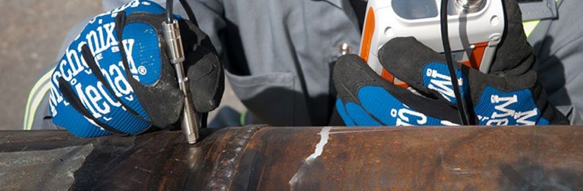
Ultrasonic Testing (UT) utilizes a high frequency, high energy cone of sound from a probe to “scan” the interior of a component for volumetric flaws or discontinuities. The sound wave travels within the component and reflects off any internal features, including the walls of the component and any defects within it. An echo that is reflected earlier on the CRT screen is a sign of a discontinuity at that location. By moving the probe in a methodical manner across the surface of the component, an operator can not only measure the thickness of the component (Ultrasonic Thickness Gauge Measurement), but also detect any defects within it. UT is often deployed to detect internal discontinuities in welded plate and pipes on site, and for measuring wall thicknesses of in-service pipes, boilers and pressure vessels
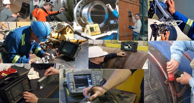
- Phase Array Method (Advanced Ultrasonic Testing)
Phase Array method is used to detect discontinuities such as cracks or flaws and thereby determine component quality. It can also be used for detecting wall thickness reductions due to corrosion, erosion and abrasion.
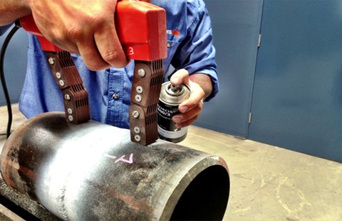
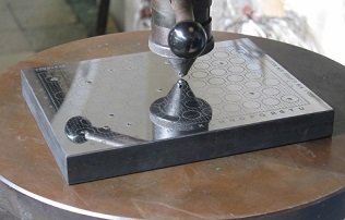
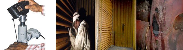
Magnetic Particle Test (MT), is an NDT method that utilizes magnetic fields to reveal surface and slightly sub surface discontinuities in any material that can be magnetized. The technique relies on magnetic fields that are either introduced into the component or generated within the component itself via an electrical current. MT is a very effective method of detecting surface cracks in welds, castings and forgings, and often more tolerant of poor surface conditions, making it ideal for inspecting in-service components. For high sensitivity requirements, such as in detecting fine fatigue cracks, the more sensitive Florescent MT technique can be used over the standard colour contrast MT, provided a suitably dark environment can be created on site.
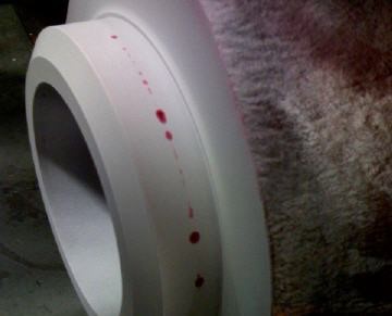
Liquid penetrant test (PT) is used to detect surface breaking discontinuities on clean, dry, non-porous materials using dyes. The dye is called the penetrant, and may either be visible or fluorescent, which then has to be conducted under ambient light (visible method) and black light (Fluorescent method) respectively. It is a relative simple technique where the penetrant is applied to the component surface and is allowed to seep into any surface breaking discontinuities, such as cracks, via capillary action. Excess penetrant is removed via cleaning, and a developer is applied, causing the penetrant to resurface, forming a high contrast indication of the discontinuity.
POSITIVE MATERIAL IDENTIFICATION
- Spark Optical Emission Spectroscopy
Optical Emission Spectroscopy, or OES, is a well trusted and widely used analytical technique used to determine the elemental composition of a broad range of metals, tubes, bolts, rods, wires, plates and many more.
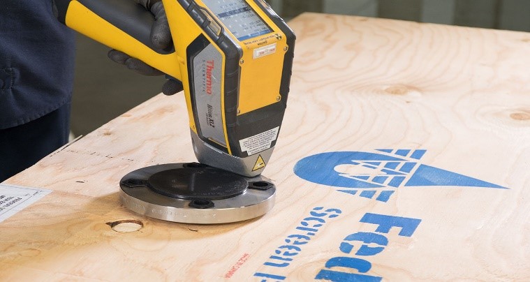
- Portable X-Ray Florescence Method
Portable x-ray fluorescence—also known as PXRF—is a portable form of elemental analysis instruments based on x-ray fluorescence technology. Portable x-ray fluorescence works just like a bench-top EDXRF instrument, but you can take it anywhere and conduct analysis outdoors, on the assembly line, in the mine, or just about anywhere else you can imagine
- Vickers (HV)
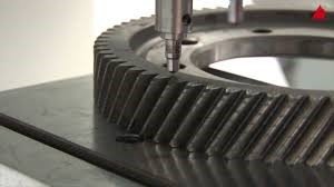
- Rockwell (RH)
Rockwell hardness test method, as defined in ASTM E-18, is the most commonly used hardness test method
- Brinell (HB)
The Brinell method applies a predetermined test load (F) to a carbide ball of fixed diameter. The resulting impression is measured, and then converted to a Brinell hardness number.
FERRITE CONTENT MEASUREMENT (FERITSCOPE)
- The Feritscope operates by generating an alternating magnetic field in the sample which is proportional to the ferrite content and which the instrument can detect. The instrument, using a non-destructive magnetic methodmeasures the relative permeability of a material in the alternating magnetic field of its probe. This provides a ferrite content reading, which is largely uninfluenced by various extrinsic parameters (lift-off, strain in specimen, curvature of specimen surface, thickness of welded material).
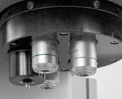
IN-SITU REPLICA METALLOGRAPHY
- In-situ Metallography refers to the examination of the microstructure of a metallic component on site. It is typically considered a non-destructive method because the area of interest does not need to be extracted for examination in a lab. In-situ Metallography will require the removal of any paint coatings and the application of light grinding followed by etching before examination can be carried out. Examination of the polished and etched surface can then be carried out immediately by using a portable microscope with attached digital camera or alternatively, by making a replica of the microstructure using special resins or plastics followed by examining the replica in a laboratory.
- In-situ Metallography can be used to determine the ferrite to austenite ratio in duplex stainless steel, estimate grain size in carbon and stainless steels as well as examining the general macrostructure and microstructure of a component. It has applications in examination of boilers, heat exchangers and reactors during annual shutdown maintenance, check the effects of post weld heat treatment processes on site, and to verify weld microstructure of very large fracture mechanics (CTOD) specimens prior to notching.